Energy harvesting with solar panels has now a competitive price to the others, and have become very popular in the world. While development of more efficient solar cells is most significant, control engineering also plays an important role in practical use of solar panels to support efficient energy harvesting.
Any solar panel has a terminal just like a battery; it has a plus lead and a minus lead. You can guess that you will have a light if you connect a light bulb with a solar panel under sunshine. Yes, it's true, even if it's difficult to predict how bright it is. But you would have a question what will happen if you put light bulbs in series or parallels.
Suppose first you have an independent voltage source, that is, an electric power supply which can supply a constant voltage whatever you connect to it. In this case, the light strength of light bulbs in parallels is same as of a light bulb, and the light strength of light bulbs in series is less than of a light bulb. To be precise but simple, we consider electric circuits with resistors instead of light bulbs below.
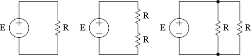
Obviously currents at voltage sources are E/R, E/(2R) and 2E/R, respectively. So powers at them are (E^2)/R, (E^2)/(2R) and (2E^2)/R, respectively. They are different each other, but it is common that you can pull more power by using small resistance. Indeed, you can get power as much as you want. Of course, such a situation occurs because we assume we have ideal independent voltage source.
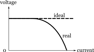
More realistic situation is that we put limitation on power of voltage sources. It is figured below. Ideal voltage sources output a constant voltage independent on current. On the other hand, real voltage sources can't keep voltage as current increases.
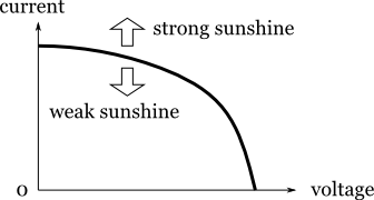
 Solar panels should be regarded as real voltage sources, and have characteristics described in the graph, called I-V curve of solar panel. Usually a plot with vertical axis of current and horizontal axis of voltage is used. Actually, the curve changes as sunshine does.
 With the I-V characteristic described in the curve above, connect the solar panel with a resistive load with resistance R. Let voltage and current of the solar panel be V1 and I1 respectively, and let voltage and current of the resistor be V2 and I2, respectively. We have already the relation between V1 and I1 in the curve above. We have a line by Ohm's law. Since we connect directly the solar panel to the load, we have V1=V2 and I1=I2. Therefore we draw the curve and line in one graph as follows.
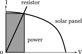
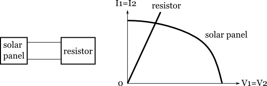 Then the common voltage V and current I are determined by the intersection of the curve and line. Now we see power generated by solar panel which is equal to power at the load in this case. Power is defined by the product of voltage and current, we know the power is equal to the area of rectangular described below.
 If you change the load to a resistor with bigger resistance, you will have another power as below.
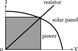 You see the latter has bigger power than the former. That means that generated power depends on the resistance of the load even if strength of sunshine is the same. This situation is the point sharply different from the case of ideal independent voltage sources
In many cases you are given a load. If you simply connect it to a solar panel, you will get power at the intersection of two curves, not as you want. In addition, strength of sunlight will continuously change, and the intersection will move unrelated to your intention. To settle this undesirable situation, we have to put a mediator between the solar panel and load.
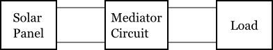
The mediator circuit plays an important role to absorb the difference between an ideal load for the solar panel and the load there. In order to avoid power loss at the mediator, we use a switching circuit. Although there are many types of switching circuits, we had better avoid a type with a switch at the input (the side of solar panel).
Although IC's driving switching circuits are available in the market, we shall use a microcontroller or FPGA to drive the circuits, because we take care of changing sunshine. Monitoring and feeding back the voltages and currents in the circuit, we try to control the system to the best working point. That means that we would like to keep the working point of solar panel at the maximum power generation, and simultaneously, to avoid power loss at the circuit, and to deliver nearly 100 percent power to the load, independently on the time-varying strength of sunlight.
- Monitor the I-V curve of solar panel, hopefully when the system is working (online monitoring)
- Decide the control specification numerically to aim the best
- Select the type of switching circuits to meet the specification
- Store data on change of strength of sunshine, or many sets of I-V curve as time goes, and analyze them to decide the specification
- Design your control law to meet the specification; that will include both of feedforward and feedback strategies
- Given nonresistive load, what can we do? If you want to charge electricity to batteries, it is not reasonable to assume resistive loads.