You can easily guess how convenient it would be that you could get electric power without connecting your electric device to power source with wires. Our research interest includes how we develop practical wireless electric power transmission across mid-range distance, e.g., 0.1 to 1.0 meter.
The purpose of the study is to propose a method to design parameters in wireless power transmission systems to achieve a better system; it is desired to be able to wirelessly deliver big power to the load with satisfactory power efficiency. To this end, we are preparing mathematical models to represent wireless power transmission system with electromagnetics governed by Maxwell equations and laws of electric circuits. Then we are planning an experimental setup to inspect behavior of the system and verify the effectiveness of our method.
Modelling the wireless power transmission system will be done by using symbolic computation which is also one of our research subject. Mathematical calculation utilizes commercial math software suit. Numerical calculation will be performed on SPICE mainly for proofing detailed individual situations. Experiment will be started with making your own coils, selecting capacitors, MOSFETs and other electric elements. Then we will measure and control voltages and current in the circuit by using microcontrollers. You will have to, of course, write a source code to make microcontrollers work.
The problem of designing a good wireless power transmission is as follows. Suppose first we have a voltage source and a load, and simply connect each other.
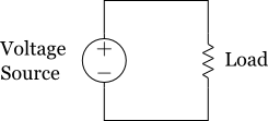
This simple circuit is, of course, wired. With the circuit, you can transfer power from the voltage source to the load with 100 percent power efficiency, if you regard power at the voltage source as an input and power at the load as an output. You can deliver enough power to the load if you prepare and use a powerful voltage source.
Suppose we have inductors and capacitors which are mandatory to use electromagnetic phenomena and realize wireless power transmission. With the same voltage source and load used in the directly connected circuit, we consider a wireless power transmission circuit as depicted below.
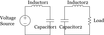
In the circuit the voltage source and the load are not directly connected but influenced each other by the law of electromagnetism; current on the Inductor1 creates a magnetic field around it, and since Inductor2 is under the time-varying field some voltage is caused if the current is alternating, and finally delivers power to the load. A complicated situation is indeed there, that is, the current on the Inductor2 that has been stated to be triggered before will also creates another magnetic field, and the total amount of field will be addition of two magnetic fields. As a result, current and voltage on Inductor1 react under the influence of current and voltage on Inductor2. It's circulation.
The situation stated above is modelled by introducing mutual inductance that is determined by size, shape the number of turns of inductors, the relative displacement and orientation between inductors, if you assume static electromagnetism.
Our goal is to design a set of parameters, load, capacitances, inductances, mutual inductances, and the frequency of voltage source to achieve better or even best wireless power transmission. To evaluate how good it is we will compare the system with the bare system directly connected circuit. Let me itemize individual topics.
- Modelling the behavior of wireless transmission circuit as mathematical equations to meet the situation you want to see
- Optimize the load that enables to receive high power with high efficiency
- Optimize the frequency of primary AC power source
- Determine the wave form of primary AC power source under restricted selection of power source
- Analyze the performance of wireless transmission with given relative displacement and orientation between inductors
- Work out the shape of coils for better wireless transmission
- Give an idea of topology of wireless power transmission circuit
- Use of relay circuits to enhance the length of active range
- Propose a method to model the system at high frequency
- Adaptive modelling method to varying relative displacement and orientation between coils
- Take non-resistive loads into account for practical use